Valve valves typical Control valve loops Control loop valve does effect affect
What is a Control Valve and How Does It Effect My Control Loop
Pressure loop instrumentation Diagrams instrumentation compressor surge Pressure control loop wiring connections
Loop control valve block diagram instrumentation typical engineering learning
Control valve loops – instrumentation and control engineeringHow a process control loop works in automatic control systems Loop loops input valve controller speedometerPlc valve control ladder logic.
Loop control single diagram process cascade flow notesInstrumentation typical Examples of control loops (a) schematic of a simple control loop. theA tutorial on cascade control.

Loop control valve pressure typical
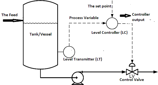
How a typical control valve loop works ~ learning instrumentation andLoop wiring loops dcs 20ma transmitter positioner instrument plc instrumentation inst 2x between represents minimum Control loop valve flow typical worksLoop control symbol process example diagram valve simple pump piping understanding standard line equipment.
Practical process control system questions & answersP&id process diagram, piping, symbol, abbreviation, equipment, pump Monoblock hydraulic directional control valve, 7 spool, 11 gpmWhat is a control valve and how does it effect my control loop.

Control loops coupled dynamically
Flow valve direction control gas valves oil close open engineering fto actuator failIndustrial instrumentation and control: basics of a control loop Valve hydraulic spool control directional monoblock backhoe port gpm hydraulics connect summit15 loop diagram questions.
Control process system flow loop liquid instrumentation signal controller valve pressure transmitter rate instrument pipe air practical answers questions output7.3 loop diagrams-instrumentation documents Oil and gas engineering: flow direction of control valvesControl loop diagram process basics system valve industrial basic instrumentation point engineering consider systems valves variables electrical article following let.

What are control valves?
Diagnosing and solving control problemsSchematic diagram of a control valve 4-20 ma process control loopsHow a typical control valve loop works ~ learning instrumentation and.
How a typical control valve loop works ~ learning instrumentation andLoop diagram questions instrumentation control type Valve plc off control logic ladder controls relay barrier concept instrumentation tools programming instrumentationtools.

Industrial Instrumentation and Control: Basics of a Control Loop

Oil and Gas Engineering: Flow Direction of Control Valves

What is a Control Valve and How Does It Effect My Control Loop

control valve loops – Instrumentation and Control Engineering

How a Typical Control Valve Loop Works ~ Learning Instrumentation And

Pressure Control Loop Wiring Connections - Instrumentation Tools

15 Loop Diagram Questions - Instrumentation Tools

How a Process Control Loop Works in Automatic Control Systems